Lewis Reeves
ELEC 2120 Signals & Systems
10/29/2024
Lab 7: Laplace Matlab
Introduction:
This lab discusses how to perform Laplace transforms using Matlab. This lab focuses on using Matlab to solve a circuit using Laplace transforms. The Matlab code will be used to solve or currents using mesh analysis, then using the currents, the output voltage will be calculated.
Procedure:
1) Find Circuit Equations in Laplace Domain
1.1 Transform circuit to Laplace domain
- First, each component is converted to the Laplace domain, and the mesh equations are found below in Figure 1.
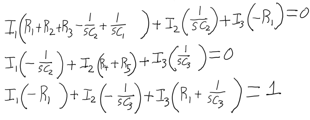
Figure 1 – Handwritten Equations
1.2 Find matrix form
- Using Matlab, the matrix is created using the derived equations from the previous step. The code used for the impedance, voltage, and current matrices are written below.A = [R1+R2+R3-1/(s*C2)+1/(s*C1),1/(s*C2),-R1;-1/(s*C2),R4+R5,1/(C3);-R1,-1/(s*C3),R1+1/(s*C3)]V = [0;0;1]I = inv(A)*V
2) Explain how the V_out equation was derived
- The V_out equation was derived using the currents across each of the resistors between the output nodes.
3) Why does the value of Np(1) show up as a zero?
- It shows up as a zero because all the other coefficients are much greater than it, so it is miniscule when compared to the others
4) Comment on the shape of the Bode plot and explain what you think it means
- The diagram is confusing, but it looks like the phase approaches zero as frequency approaches one. The shape drops exponentially, but then recovers exponentially
Conclusions:
I enjoyed solving the circuit using Matlab to make the calculations much simpler and repeatable for any input value. Something that didn’t go well was some of the add ons for Matlab had not been installed which took some time to figure out and install. I would improve the experience by explaining what tools would need to be installed on your Matlab if you are using your own computer and not a university computer.